
Technical issue discussion of composites used in submersibles
The implosion accident of a small deep-sea submersible probably remains in the memory of many people.
There was a lot of coverage in the media, partly because it happened during the Titanic deep sea voyage.
It was a very tragic accident in which five people lost their lives, but there is also a technical point of view that should be considered in the sense that it will never happen again.
This is not the part reported in the media, but I would like to talk about what should be considered “technically” from the implosion accident of the submarine.
OceanGate submersibles that have been featured in past mail magazines
I have also covered the submarine that caused the implosion accident in the past.
Although it will appear several times later, CFRP is used on the side of the pressure hull as shown in the diagram cited in the column below (the black part in the image).
*Related columns
Application of FRP to Deep Sea Submarine Cyclops (Japanese only)
During development, it was named Cyclops.
Cyclops 1 is shaped so that the observation window covers the entire front, and it can dive to a depth of about 500m.
You can see an overview in the video below.
On the other hand, Cyclops 2 is the development machine that became the predecessor of Titan that caused the implosion accident.
The structural design, which used both titanium and CFRP for the structural members of the pressure hull, was quite avant-garde, but we started actual operation while using health monitoring such as the real-time hull health monitoring (RTM) system, and started diving into the deep sea. successfully multiple times.
Composite World with a retrospective on the Titan accident
As soon as I saw the Titan news, I knew this was something I had covered before.
I saw it on TV, but I also remember that various commentators made various remarks.
Since the information was limited, there were some things that could not be helped, but there were some things that seemed to be clearly different from a technical point of view.
Meanwhile, Composite World, a North American composite material industry paper, posted an article looking back on Titan’s accident.
* Article published in Composite World
This content is very interesting, and since it was written by a person who actually interviewed OceanGate, it contains information that I myself do not know, so I learned a lot.
This time, I would like to consider this phenomenon from a technical point of view while referring to this article.
Difficult to identify the cause of the accident
Due to this Titan accident, criticism erupted even in North America, where OceanGate is headquartered.
There are many newspaper articles and videos criticizing OceanGate.
I myself have looked through some information from North America, and I found some rather harsh expressions.
In the Composite World article above, it is stated that in addition to OceanGate, there is a lot of criticism of Mr. Rush, who led the development of the submarine.
There is also information that the acrylic glass that was Titan’s peephole was the starting point of the destruction, but it seems that the main cause was the destruction of CFRP (carbon fiber reinforced plastic) used for the housing part of the pressure shell. It seems that there are many stories.
In a video critical of OceanGate, it is shown that the highest priority is to make profit by expanding the internal space of the submersible by taking advantage of CFRP’s high specific strength and specific rigidity so that it can carry as many people as possible at the same time. He said he caused an accident.
The information that the use of CFRP was aimed at reducing the cost of the constituent materials has also been criticized.
It seems that cost reduction may be the remote cause of the accident.
In fact, it is considered to be quite difficult to investigate the true cause, but one of the possibilities is CFRP (carbon fiber reinforced plastic composites).
FRP (composite) is also used in past submersibles
It is not uncommon for FRP to be used in submersibles.
Although it is a little old information, FRP is also used in Japan’s deep manned research submersible “Shinkai 6500”.
FRP is mainly used for hull skins and ballast tanks.
As the name suggests, the hull skin is a protective plate attached to the outermost side and at the same time plays a role as a rectifying shape.
The degree of freedom in shape during molding of FRP is utilized.
The hull skin is made of GFRP with (iso)unsaturated polyester as the matrix resin.
Manufactured by alternating layers of T-glass satin weave cloth and E-glass plain weave cloth, with a thickness of about 3.5 mm for 12 plies.
I believe that the use of glass fiber is from the standpoint of impact resistance.
Since it is an outer skin rather than a pressure hull, pressure resistance is not required.
On the other hand, the ballast tank used CFRP with carbon fiber as the reinforcing fiber to withstand the pressure during drainage.
However, the outermost layer is GFRP with glass fiber as the reinforcing fiber.
The reason is that the outermost layer of the ballast tank is in contact with another structural member, titanium.
This is to avoid “electrical corrosion” because carbon fiber is conductive.
I have touched on electrolytic corrosion due to CFRP in past columns.
*Related columns (Japanese only)
FRP for the first time – Necessity and precautions of FRP repair process
The matrix resin of the above ballast tank is also unsaturated polyester.
We believe that this is because it is easy to perform “hand layup”, which is the adopted FRP layup/molding process.
Shinkai 6500 adopts titanium alloy instead of FRP for pressure hull
It should be noted here that the Shinkai 6500 did not use FRP for the pressure hull.
As already mentioned, OceanGate’s Titan pressure hull is a hybrid of titanium and CFRP.
I imagine that such a difference is one of the motivations to suspect that CFRP may be one of the causes of Titan implosion.
OceanGate’s Rush’s story of “breaking some conventions (rules, rules) to make Titan” is also written in the Composite World article referenced.
Among the stories of breaking this convention is a pressure hull that uses a combination of titanium and CFRP.
What is the assumed cause if CFRP destruction was the main cause of Titan implosion?
If the cause of the Titan implosion accident was CFRP, I would like to think about what caused it.
Composite World article claims
It is said that the cause is that it was used where a compressive load is applied.
In other words, in the case of continuous fiber CFRP, where the fibers are not cut in the middle, the reinforcing fibers secure the load in the tensile direction, so it has very high strength and rigidity. The main argument is that if the force of the compression system is applied in the direction, the characteristics cannot be utilized.
I think the point is that it is not easy to withstand a strong water pressure of 4,993 psi (approximately 350 kgf/cm2).
I would like to express my thoughts on this topic.
Discussion if Titan implosion caused by fatal fracture of CFRP
I would like to express my thoughts below.
Composite World has a point
The first thing to say is that Composite World has a point.
Certainly, in compression, the strength of continuous fiber CFRP of medium-elasticity, high-strength PAN-based carbon fiber is reduced to about 1/3 to 1/4 of that in tension.
I think you are pointing out a good point.
In fact, it is more appropriate to use FRP for loads such as high-pressure tanks and pipes that apply force from the inside to the outside, that is, loads that are mainly tensile on the walls of the housing.
Less likely to break under pure compressive load alone
On the other hand, I have a question.
The water pressure is said to be 4993psi.
Assuming that this is the maximum load due to water pressure, there is no problem in terms of CFRP material properties.
More specifically, looking at the compressive breaking strength when using the above PAN-based medium-elasticity, high-strength carbon fiber, it is only about 1/20 of the data I have at hand.
Perhaps the biggest problem with fracture is;
“Pure in-plane compression did not apply load.”
I think this point is technically important.
Compressive properties of FRP can only be obtained from in-plane properties in material tests.
As I have repeatedly said in lectures, seminars, and guidance at clients;
“Material properties cannot be obtained unless in-plane and out-of-plane are separated.”
The word “anisotropy of FRP” stands in the way of understanding here.
The out-of-plane strength properties of FRP can be less than 1/20 of the in-plane properties.
I wonder how many people are able to answer immediately what they mean by inside and outside.
As the name suggests, in-plane is the characteristic when destruction and deformation are completed in a certain plane, and out-of-plane is the characteristic when breaking or deforming, such as breaking away from or sinking into the plane.
Out-of-plane is also called “interlayer”. This is because it is a property related to “between” the “layers” in which the material is laminated.
I have written about this in several columns and series in the past, so please refer to that for more details.
※Related information (Japanese only)
In-plane and out-of-plane strength evaluation derived from FRP anisotropy for the first time
Symmetry/conjugacy of shear stress (Available in English)
Imagine that in this Titan, CFRP, or combined titanium, acrylic glass, etc., were “deformed” by water pressure.
As a result, the load generated in CFRP is a complex mode combining in-plane and out-of-plane.
For example, imagine an empty aluminum can.
If you continue to apply force to one part of the “ring”, which is the edge of the mouth, the ring will deform greatly somewhere.
It is an image that the circle of the edge of the aluminum can is crushed.
When this kind of deformation occurs, the deformation that should have been applied only to the edge part extends to the side of the aluminum can.
It was difficult to explain with just words, so I tried to reproduce it using empty cans I had on hand.
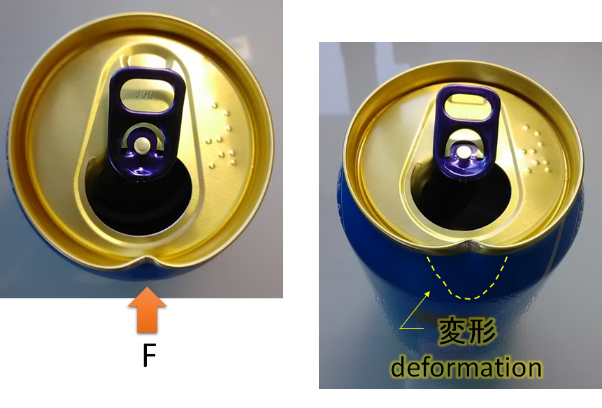
It can be seen that the direction and position of force applied by F, and that the deformation of the circular end extends to the side (outline area indicated by the yellow dashed line).
This is exactly the lateral, combined in-plane and out-of-plane loading mode.
When this phenomenon occurs, it is highly probable that the origin of FRP failure will be the “loading mode of interlaminar shear”.
Please understand that deformation occurs locally where there is a large deformation, rather than looking at it macroscopically (overall).
The interlaminar shear property value is less than 1/20 of the tensile property value of the PAN-based CFRP mentioned above.
And even if you use fibers and resins with fairly high property values, it will be a marginal line whether it can withstand water pressure or not.
In this way, I believe that the interlaminar shear load caused by minute changes in the parts associated with CFRP was one of the factors that triggered the final failure of CFRP.
In-plane vs. out-of-plane discussion is not possible by bending tests
Many people misunderstand that the “bending test” is good because it can evaluate these properties together, so the above argument cannot be made.
This is because the form factor is too large when the in-plane and out-of-plane properties are mixed, and the material properties alone do not converge.
That is why the flexural properties depend on the shape parameters of the specimen.
Behavior against fatigue
The concept of repetitive fatigue is also essential.
We cannot deny the possibility that the implosion was caused by the progress of fracture due to repeated fatigue of Titan.
Of particular importance to understand is the difference between LCF and HCF.
LCF stands for Low Cycle Fatigue and HCF stands for High Cycle Fatigue.
LCF is an evaluation of repetitive fatigue that occurs for each event, and HCF is an evaluation of repetitive fatigue that occurs unavoidably during operation.
This time I’m concerned about LCF.
In terms of Titan, it is the number of dives.
It takes one cycle from being submerged once to being pulled up.
This LCF often has significantly higher stress levels than HCF and can lead to early failure of the FRP.
It would be nice if the decrease in allowable stress stopped due to the Kaiser effect, but FRP is generally said to have no fatigue limit, and there is a risk that LCF may cause the fracture to progress, albeit minutely.
*Related columns (Japanese only)
Examination of CFRP soundness evaluation by AE based on Kaiser effect
It is quite possible that the accumulation of such microdamages will lead to the abrupt final failure of the FRP.
After all, the structural design of FRP requires the element of fatigue design that incorporates the concept of probability centered on regression analysis.
※Related information (Japanese only)
“Mechanical Design” Series 32nd Influence of FRP Internal Damage on Dynamic Fatigue Properties
Goodman diagram important for CFRP and GFRP design
How do you think about this article?
This time, referring to a tragic accident in which a human life was lost, I would like you to understand how important technical considerations are to prevent recurrences, and I have developed some of the technical considerations.
Sometimes, even with technology, failure is inevitable.
The important thing is to face the fact rather than just criticize it, and consider how to prevent the same thing from happening again.
This is something that only engineers and researchers can do.
I hope that engineers and researchers around the world will take on such efforts.