
Symmetry/conjugacy of shear stress
The anisotropy of FRP (composites) is very pronounced compared to other materials, it affects not only strength and stiffness, but also the coefficient of linear expansion. Understanding FRP anisotropy is an absolute requirement for those who work with FRP.
On the other hand, even if you know that FRP materials have anisotropic properties, it is not easy to understand them when you actually perform stress analysis.
However, when the people who actually perform the stress analysis are different from those who understand the anisotropy of FRP, there are many cases where only calculations are performed without a proper understanding of the anisotropy of FRP.
I feel that one of the reasons for this is that people in charge of CAE do not understand the basics of the finite element method at the same time as they do not have a good understanding of the material called FRP.
Today, I would like to go back to the basics of the finite element method and think about the symmetry/conjugation of shear stress, which can be said to be the first step in understanding the anisotropic material FRP.
Three-dimensional diagrams absolutely indispensable for understanding FRP
Have you ever heard of a three-dimensional diagram of stress?
If you can visualize the figure below, for example, you should have no problem.
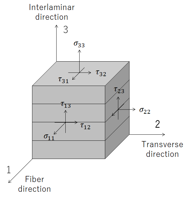
Image above was drawn by FRP Consultant
The axis is 123 instead of xyz, which is a notation commonly used in the world of mechanical design.
In the FRP world, the uniaxial direction (x-axis direction) is often used as the fiber direction.
And τ (tau) in the figure is shear stress.
Symmetry/conjugacy of shear stress means as shown below.
τ12=τ21
τ23=τ32
τ13=τ31
You may be familiar with this relationship.
However, those who can say exactly how this is calculated may be in the minority.
To grasp the basics of the technique, it is necessary to think carefully about each of them, I would like to go back to the basics of the finite element method and describe this relationship again from the basics.
Think in terms of moment equilibrium in the micro region
As is the case with many reference books, let’s consider this in two dimensions, since three dimensions would increase the number of parameters.
Imagine 12 planes (XY plane) viewed from 3 axes (Z axis).
If we define a micro-region (vertical: dy, horizontal: dx) here, the stress on each side will be as shown in the figure below.
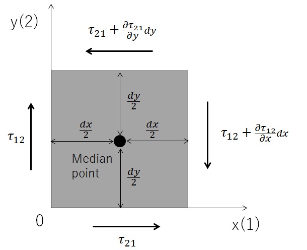
Image above was drawn by FRP Consultant
The partial differentiation is due to the stress gradient in each axis, for example, dx away from one axis (X-axis), and the change in the gradient is added.
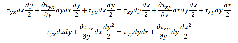
If the center of gravity of the micro-region is specified as shown by the black circle in the figure, the “balance” of moments around the three axes (Z-axis) passing through the center of gravity, that is, the axes in the front-to-back direction from the screen, can be calculated as shown in the equation below.

The names of the axes 1 and 2 make it difficult to define derivatives and partial derivatives, so all of them are rewritten as xy.

This can be expanded as follows.
Dividing both sides by dxdy yields the following equation.

Furthermore, if we take the limit value so that the micro region becomes 0, we obtain the following equation.
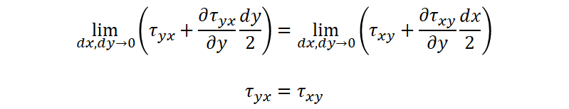
In other words, if we return the names of the axes to 1 and 2, we can achieve the result below.
τ21=τ12
This is the very “symmetry/conjugacy of shear stress” shown at the beginning of this section.
The other axes can be calculated in the same way.
What is important is not only understanding the theory, but also how to put it into practice.
In order to avoid grasping things intuitively, I explained it while including theoretical formulas.
In an academic sense, repeating such an approach is a good idea, but it is far more important to understand how to put these into practice when putting them into practice as a technology.
Positive impact on the design of laminate configurations to be employed in material testing
The first thing to understand is;
“The application of shear stress symmetry/conjugacy opens up a wider range of stacking options for the specimen to be evaluated.”
One example is to obtain the characteristic value of interlaminar shear, which is said to be the main cause of FRP failure.
To evaluate this property, the specimens must be stacked very thickly.
One can imagine that a thicker specimen would be necessary to obtain the interlaminar out-of-plane shear properties.
However, the shear properties of the specimen are
τ13=τ31
we can understand that the lamination configuration can be changed by simply knowing that τ13=τ31.
By changing the stacking configuration based on the above idea, the number of FRP material ply numbers to be stacked can be reduced by a factor of several (a few times).
For details, please refer to reference books and test standards, but this kind of thinking is possible depending on whether or not you know the symmetry and conjugation of shear stresses.
Understanding of characteristic input values to CAE taking anisotropy into account
An understanding of the basics of the finite element method introduced this time leads directly to an understanding of CAE condition settings.
If this becomes possible, the accuracy of various simulations will increase.
In addition, we understand that material property values in each direction are important in order to consider anisotropy, so it is expected that this will lead to improved risk management ability to determine where to pay attention.
Conversely, if you do not notice the anisotropy in the symmetry/conjugation of shear stress as introduced, you will hardly have any doubts about the handling of material property values when performing CAE.
The lack of basic knowledge introduced in this article may be one of the reasons why one cannot perceive the importance of out-of-plane deformation, which is the main failure mode of FRP, especially the interlaminar shear characteristics already mentioned.