
Composite fiber alignment measurement by Talbot-Lau Interferometer
Today I would like to introduce new technology for composite fiber alignment analysis.
This technology was developed by Japanese global company, KONICA MINOLTA ( https://www.konicaminolta.com/selector/index.html ).
They produce office products such as photo-related products and copiers, and medical equipment.
Why Talbot-Lau Interferometer is developed?
New type of X ray inspection system, Talbot-Lau Interferometer, has been released to image cartilage for rheumatoid arthritis diagnosis.
In order to monitor the progress of rheumatoid arthritis, and checking the effects of treatment, diagnostic imaging of cartilage seem to be very important factor. Also, current main instrument for the diagnosis, MRI, leads to long time capture and very high cost.
New Talbot-Lau Interferometer system has been developed to achieve the goal of fast and low-cost diagnosis.
The measurement principle can be reviewed as below.
(ref: https://www.konicaminolta.com/about/research/healthcare/talbotlau.html )
——————-
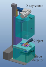
( The image above was referred from https://www.konicaminolta.com/about/research/healthcare/talbotlau.html?)
The principal feature of this device is that, by using three X-ray gratings (G0, G1 and G2 in the diagram), the refraction of the X-rays by the subject is made visible in the form of moire patterns.
Emitted downwards from an X-ray source deployed at the top, the X-rays pass through G0, then through the subject, through G1 and G2, finally arriving at the X-ray detector. By passing through G0, the X-rays are phase-aligned. When the phase-aligned X-rays pass through the subject above G1, the subject produces phase changes, which are then reflected in the moire patterns formed when the X-rays pass through G1 and G2. These moire patterns are then detected by the image detector, and the pattern data is subjected to arithmetical processing. As a result, three images are generated: an absorption contrast image, a differential phase contrast image, and a visibility contrast image.
——————-
Approach to inspect composite fiber alignment
They are now trying to apply this technology to measure fiber alignment of composites.
Summary can be reviewed in the page blow.
https://www.konicaminolta.com/jp-ja/phase-contrast/
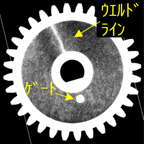
If composite parts are put on turn table in Talbot-Lau Interferometer, the interference image was changed by refraction angle difference among reinforcing fibers, matrix resins, and voids.
The system can create the contrast by differential phase image. As a result, fiber alignment can be colored mapped, and voids can be detected.
Welding line and gate can be also inspected.
Gear images are shown in the page above by black and white image.
( The image above was referred from https://www.konicaminolta.com/about/research/healthcare/talbotlau.html )
Similar system was introduce in last year as below, but Talbot-Lau Interferometer inspection system is totally different and could inspect inside of fiber alignment because the image was transmission one.
Understanding the fiber alignment is important for composite design.
Anisotropic properties of composites should be controlled by design practice to avoid unexpected fractures in the field.
Such kind of new inspection technologies would be the candidate to evaluate it.